Matrix Creation for Circuit Calculations
Posted: 07 Dec 2022, 18:12
Meanwhile I'm confused how to set up equations for the matrix to calculate the coil values via CircuitsAndDynamics. Afters some tests by hand and the CircuitBuilder, I still have a deviation of the matrix B and open questions.
Simple Example:
https://github.com/ElmerCSC/elmer-elmag ... ent_source
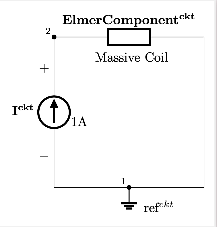
Equations from CircuitBuilder:
1. -Is + Icoil = 0
2. +Us - phi2 = 0
3. -Ucoil + phi2 = 0
4. Is = Is(t)
As I understood, i have to create the network equations for Kirchhoff 1/2 and the component equations. My try was:
Kirchoff 1 (KCL):
1. Is - Icoil = 0
Kirchoff 2 (KVL):
2. -Us + Ucoil = 0
Component (or Potential):
3. -phi2 + Us = 0
4. -phi2 + Ucoil = 0
5. Is = Is(t)
With that way more complex circuits are correct with CircuitBuilder. But in this case i have an additional equation.
In addition, the question for the 2D case: If I have several coils, each with a positive / negative side, then I have combined all the positive coil sides for e.g. phase 1 in one body (analogously for the negative side). Is it also possible to go this way for the circuit simulation or is it smarter to look at each coil individually in the circuit (2 coils (bodies) each with a positive and negative side are then 4 components (bodies) with the circuit solver)?
Simple Example:
https://github.com/ElmerCSC/elmer-elmag ... ent_source
Equations from CircuitBuilder:
1. -Is + Icoil = 0
2. +Us - phi2 = 0
3. -Ucoil + phi2 = 0
4. Is = Is(t)
As I understood, i have to create the network equations for Kirchhoff 1/2 and the component equations. My try was:
Kirchoff 1 (KCL):
1. Is - Icoil = 0
Kirchoff 2 (KVL):
2. -Us + Ucoil = 0
Component (or Potential):
3. -phi2 + Us = 0
4. -phi2 + Ucoil = 0
5. Is = Is(t)
With that way more complex circuits are correct with CircuitBuilder. But in this case i have an additional equation.
In addition, the question for the 2D case: If I have several coils, each with a positive / negative side, then I have combined all the positive coil sides for e.g. phase 1 in one body (analogously for the negative side). Is it also possible to go this way for the circuit simulation or is it smarter to look at each coil individually in the circuit (2 coils (bodies) each with a positive and negative side are then 4 components (bodies) with the circuit solver)?