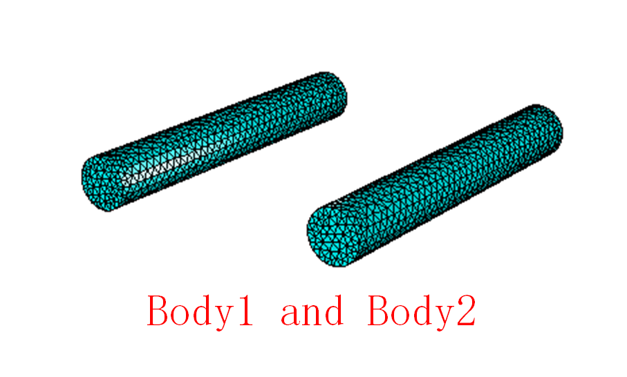
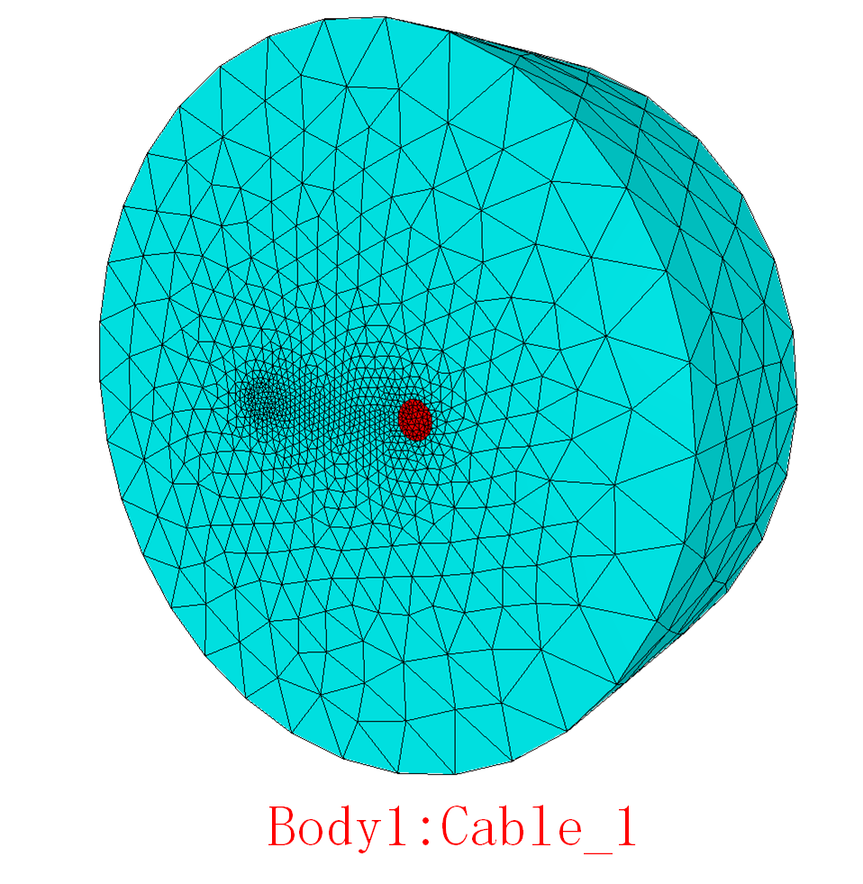
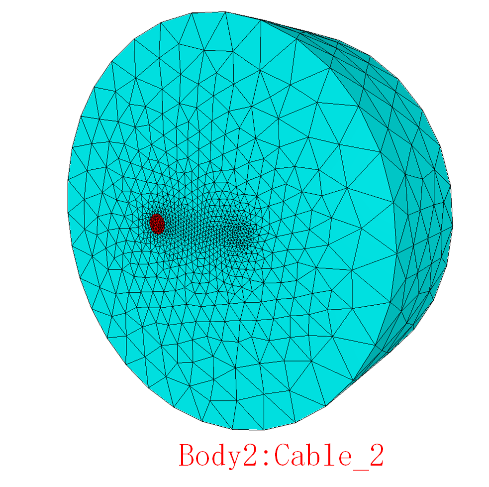
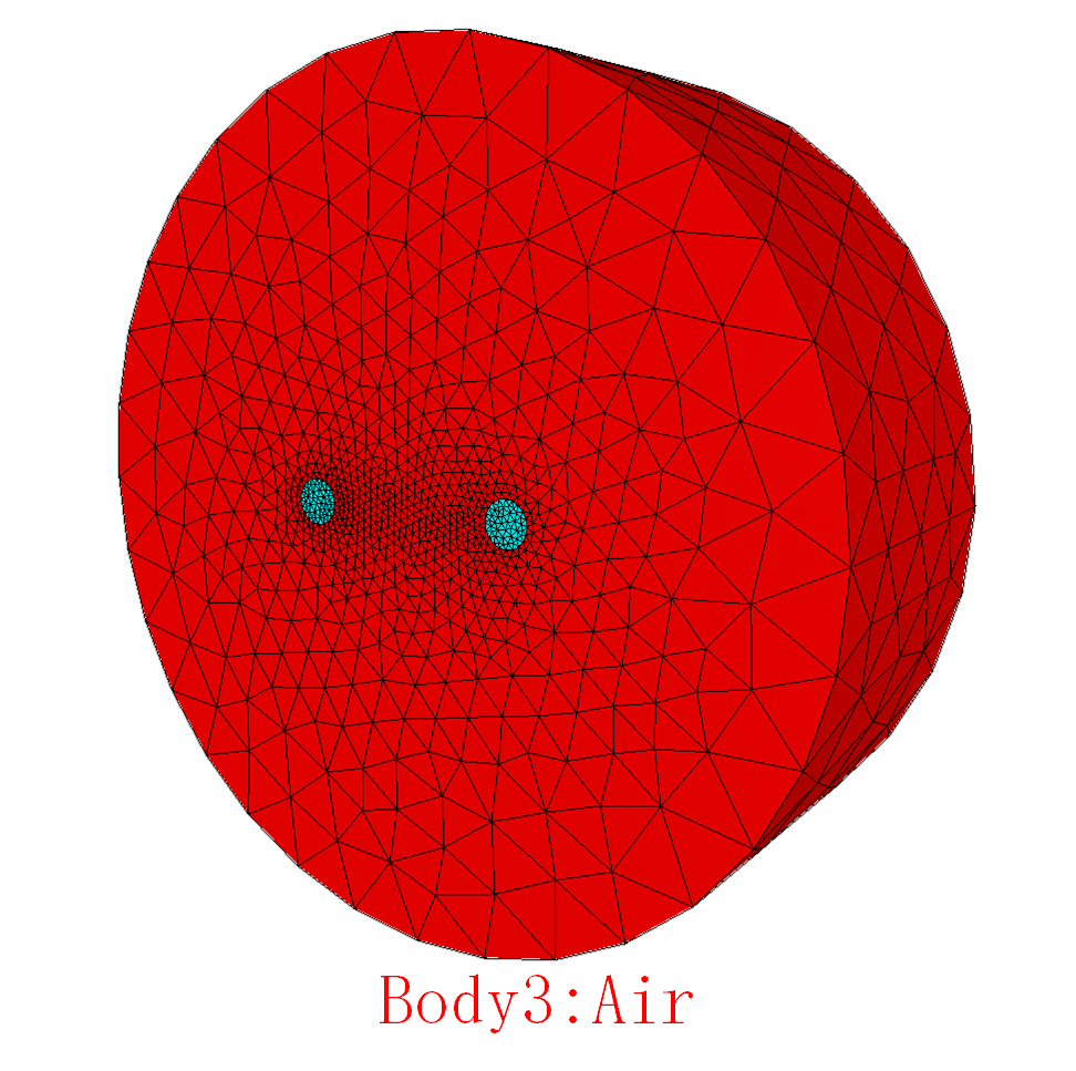
I build a 3d model with two cables and air.Cable_1 series connection with current source, and I want to calculate the induced current in Cable_2.How could I set Cable_2 in "circuits.definitions"?(I need induced current could flowing through Cable_2)
The sif:
Code: Select all
! A simple testcase for testing CircuitsAndDynamics module.
! Author: Eelis Takala, Trafotek Oy
! Original date: October 2015
! eelis.takala@trafotek.fi
Check Keywords "Warn"
INCLUDE 1962-circuits.definitions
Header 1
   Mesh DB "." "."
End


Simulation 1
   Max Output Level = 5
   Coordinate System = Cartesian 3D
   Coordinate Mapping(3) = 1 2 3
   Coordinate Scaling = 0.001
   Simulation Type = Steady
   Steady State Max Iterations = 1
   BDF Order = 1
   Output Intervals = 1
   Angular Frequency = 314.159265359
!   output file = "runoutput.dat"
End

Constants
  Gravity(4) = 0 -1 0 9.82
  Stefan Boltzmann = 5.670374419e-08
  Permittivity of Vacuum = 8.85418781e-12
  Permeability of Vacuum = 1.25663706e-6
  Boltzmann Constant = 1.380649e-23
  Unit Charge = 1.6021766e-19
End


Solver 1
   Exec Solver = Before All
   Procedure = "WPotentialSolver" "Wsolve"
   Equation = "Wire direction"
   Variable = W
   Linear System Solver = Iterative
   Linear System Iterative Method = CG
   Linear System Max Iterations = 10000
   Linear System Convergence Tolerance = 1.0e-10
   Linear System Preconditioning = ILU0
   Linear System Abort Not Converged = True
   Linear System Residual Output = 1000
End
Solver 2
   Exec Solver = Always
   Equation = Circuits
   Variable = X
   No Matrix = Logical True
   Procedure = "CircuitsAndDynamics" "CircuitsAndDynamicsHarmonic"
End
Solver 3
   Equation = "MGDynamics"
   Variable = "A[A re:1 A im:1]"
   Procedure = "MagnetoDynamics" "WhitneyAVHarmonicSolver"
   Angular Frequency = 314.159265359
   Export Lagrange Multiplier = Logical True
   Linear System Symmetric = Logical True
   Linear System Complex = Logical True
   Linear System Solver = Iterative
   Linear System Iterative Method = BicgstabL
   Linear System preconditioning = Circuit
   Linear System Convergence Tolerance = 1.e-7
   Linear System Max Iterations = 3000
   Linear System Residual Output = 1000
   BicgStabL Polynomial Degree = 4
   Linear System Abort not Converged = True
   Steady State Convergence Tolerance = 1e-06
End
Solver 4
   Equation = "MGDynamicsCalc"
   Procedure = "MagnetoDynamics" "MagnetoDynamicsCalcFields"
   Linear System Symmetric = True
   Potential Variable = String "A"
   Calculate Current Density = Logical True
   Loss Estimation = Logical True
   Steady State Convergence Tolerance = 0
   Linear System Solver = "Iterative"
   Linear System Preconditioning = None
   Linear System Residual Output = 1000
   Linear System Max Iterations = 5000
   Linear System Iterative Method = CG
   Steady State Convergence Tolerance = 1e-6
   Linear System Convergence Tolerance = 1.0e-8
End
Solver 5
   Exec Solver = Always
   Equation = "ResultOutput"
   Procedure = "ResultOutputSolve" "ResultOutputSolver"
   Output File Name = 1962-results
   Vtu format = Logical True
   Save Geometry Ids = Logical True
End
Solver 6
   Exec Solver = Always
   Equation = Circuits Output
   Procedure = "CircuitsAndDynamics" "CircuitsOutput"
End
Solver 7
   Exec Solver = Always
   Equation = "sv"
   Procedure = "SaveData" "SaveScalars"
   Filename = 1962.dat
End

Equation 1
   Active Solvers(4) = 1 2 3 4
End


Material 1
   Name = perm1e1
   Relative Permittivity = Real 1
   Electric Conductivity = Real 3.0e7
   Relative Permeability = Real 1
End

Material 2
   Name = air
   Relative Permittivity = Real 1
   Electric Conductivity = Real 0
   Relative Permeability = Real 1
End
Material 3
   Name = aluminium
   Relative Permittivity = Real 1
   Relative Permeability = Real 1
   Electric Conductivity = 3.07e7
End


Body 1
  Target Bodies(1) = 1
  Name = "Body 1"
  Equation = 1
  Material = 3
  Body Force = 1
  Body 1 = Logical True
End

Body 2
  Target Bodies(1) = 2
  Name = "Body 2"
  Equation = 1
  Material = 3
End

Body 3
  Target Bodies(1) = 3
  Name = "Body 3"
  Equation = 1
  Material = 2
End

Component 1
   Name = String L1
   Master Bodies = Integer 1
   Coil Type = String massive
   !Foil Winding Voltage Polynomial Order = Integer 1
   !Circuit Equation Voltage Factor = Real 0.5 !symmetry (half of the problem is solved)
End


Body Force 1
   Name = "Circuit"
   testsource Re = Real 1
   testsource Im = Real 0
End


Boundary Condition 1
   Name = BCn Flux Parallel
   Target Boundaries(7) = 2 3 4 6 7 8 9
   A re {e} = Real 0
   A im {e} = Real 0
End

Boundary Condition 2
   Name = ground
   Target Boundaries = 5
   W = Real 0
   !A re {e} = Real 0
   !A im {e} = Real 0
End

Boundary Condition 3
   Name = current in foil winding
   Target Boundaries = 1
   W = Real 1
   !A re {e} = Real 0
   !A im {e} = Real 0
End
Code: Select all
$ Circuits = 1


! ------------------------ Circuit 1 ------------------------
! Define variable count and initialize circuit matrices.
$ C.1.perm = zeros(4)


$ C.1.variables = 4
$ C.1.A = zeros(4,4)
$ C.1.B = zeros(4,4)
$ C.1.Mre = zeros(4,4)
$ C.1.Mim = zeros(4,4)

! Define variables.
$ C.1.name.1 = "i_testsource"
$ C.1.name.2 = "v_testsource"
$ C.1.name.3 = "i_component(1)"
$ C.1.name.4 = "v_component(1)"

! Define sources:
!------------------
$ C.1.B(0,0) = 1
$ C.1.source.1 = "testsource"

! Define network cycles:
!-------------------------
!Voltage relations.
$ C.1.B(1,1) = 1
$ C.1.B(1,3) = 1
!Current relations.
$ C.1.B(2,0) = 1
$ C.1.B(2,2) = -1Any help is appreciated
Xiejinzhi